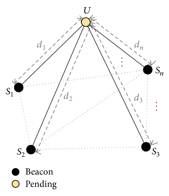
This project is to create a multi-purpose local positioning system. The only reliable system that I know of relies on multilateration using TDOA. Range is an important factor, though, since system cost scales as the sqaure root. Most UWB signals are in the 5 GHz range, which unfortunately means that they are heavily affected by obstruction. I hope that the penatrative nature of UWB compensates for this. The best bet would be to evaluate a range of active UWB technologies to investigate range and resolution capabilities as a function of cost, though, the Decawave DM1000 seems like a good compromise. Additionally, given that the ground is approximately a plane, it is possible that only 3 points will be requred for accurate trilateration, and if at points only 2 stations are available, the system should have enough "memory" to be able to resolve positions given 2 potential candidate positions. An external radio may not be required if station informtion can attatched to the payload of localisation signals. The sta tions themselves will of course require power, but it is likely that they will only be required during the day, in which case batteries could perhaps be dispensed with.
Next actions:
I talked to the client about the requirements and scope: he is interested in the applications. Namely, he likes the ability to both find specific trees, and identify trees. The cost/benefits are not precisely defined, but it seems as though it would be worth a proof of concept test.
The MVP would consist of 2 modules, each consisting of a DW1000 UWB chip, an aerial, balun etc, as well as an ATMega and LCD (and a power supply of some kind, suggest AA for the time being). This would allow a test of the ranging ability, especially through different environmental conditions (in particular, dense forest). This MVP should therefore be designed, and the parts ordered.
The design notes need to be carefully investigated, particularly with reference to the possible need for a 4 layer design, and considerations for the RF traces.
This does not look like an easy project at all. To start with, a 4 layer design will be necessary. Many external components are required, and EMI is a big deal at 3.8 GHz. The evaluation kits are unaffordable.
Somehow, I managed to forget that the DWM1000 solves all of these problems, and only costs $33.53. So, the MVP is now very easy to design. I'll see what I can do to keep the board size to a 50 mm square.
I might try to save a few dollars and weeks, and make this design also serve for a larger multilateration test. The design will need a way to measure battery voltage, a power switch, a display of some kind, an SD card reader for data storage in the tag, some kind of hardware switch to set up tag/reader/gateway statu, and a button.
Next actions:
After some conversations with the client, the completion date for this project has been defined as 2018-07-01, in time for the harvest. It will be required for the harvest, since it will greatly improve harvesting efficiency. Since it's now officially a project, it might be time to do some project management, and get this logged properly.
Radio amplifier options should be investigated in the future, since this could allow large increases in the range of the modules. Of course, ACMA's legal limits will have to be checked to ensure conformity with Australian law.
Next actions:
I gave myself a bit of a jolt by ordering a pair of DWM1000 modules through DigiKey. The schematic design is now finished, and just needs checking over. Before I go further though, it might be worth performing the project management, so as to ensure that I am actually capturing all the functional requirements. I also still need to check if modifications to this product are legal, and to what extent.
Next actions:
Have completed the first draft of the project management, I just need to check the requirements with the client. I was going to make some milestones, but too much is unknown about this project, due to the cutting edge nature of the design. Once the MVP has proved itself, and some regulatory research has been completed, it might be appropriate to lock in some more specific timelines.
The MVP just needs to provide an evaluation kit for the DWM1000, and provide a UI in the form of a screen, button (only one is required at this stage, since very little functionality is necessary), and optional buzzer, for field testing. Therefore it will also need a battery pack and power switch, as well as a USB input for serial data aquisition. The current schematic for the LPS_1.0 fulfills these requirements. Therefore, it's time to create the PCB layout.
Well, about 5 hours later and V0.1 is done. Then I'll need to count the components, do a final check over the design, and get it fabricated.
Next actions:
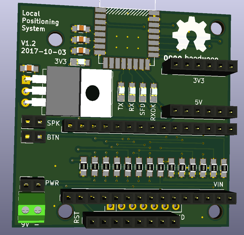
I fixed the version numbers, and featured the design on the front page for kicks and giggles. The main update I can think of is that it might be better if the voltage regulator was on the back, and maybe even some of the resistors, but I really can't be bothered. I don't think it will really make any different to the antenna propogation. The current plan is to mount the PCB with adhesive standoffs against some perspex so that the LEDs, Arduino, and screen are all visible. I also added the relevant silkscreen marks to the back of the PCB, just in case some items need to be mounted on the back.
I counted over the components required, and produced the following shopping list:
Next actions:
I made a few more changes to the design, mostly just moving things around to make assembly easier, but also adding in an LED indicator for the 3.3 V supply voltage. I've also swapped to KiCad's OpenGL canvas, which is just so much better than the default. Looking forward to playing around with that in future revisions of projects.
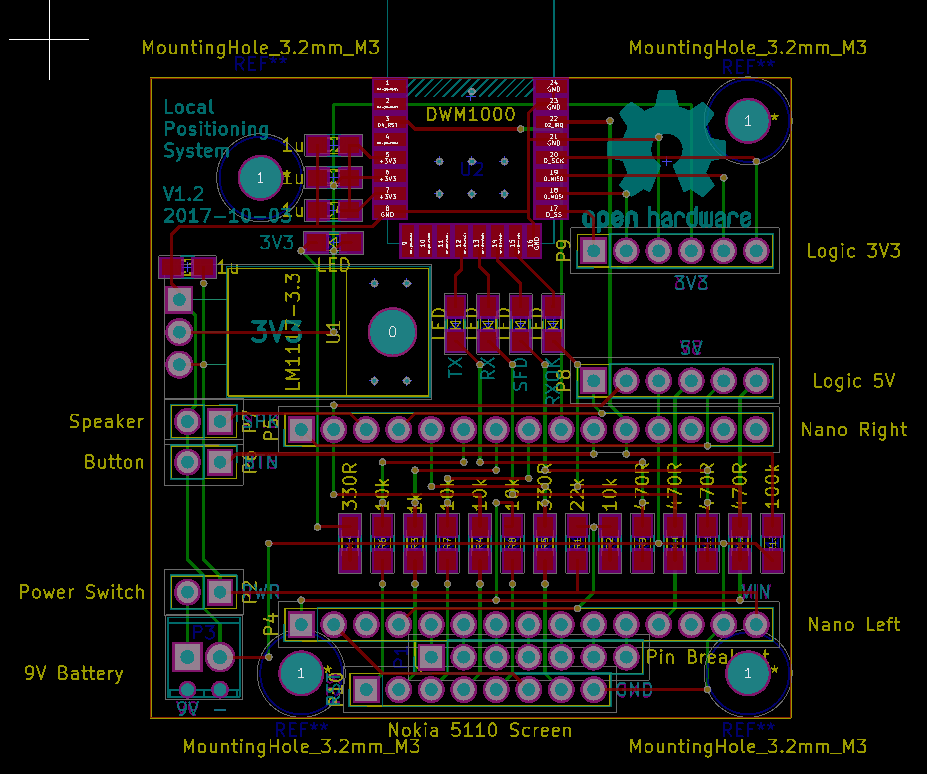
I've prepared the board for fabrication. It's sitting in the checkout, but I haven't ordered it yet, since there is a national holiday in China from the 1st to 7th of October. So, I'll leave it there, and then pull the trigger on 2017-10-08 to be ready in time for Monday at 10am. I'll wait until a week after that before I order the remaining parts, including standoffs. I'm considering using 3.18 mm holes as standard. Even though they are pretty big, it should allow me to use M3 and standoffs interchangeably. Though, many boards also use M2, so I'll need both sizes of screw. I've already bought some M3, and I just ordered some M2.
Next actions:
I was having a read into the UWB restrictions, and it seems to be roughly inline with international precedent: a 2010 proposal document suggested "-41.3 dBm/MHz EIRP and a peak power limit of 0 dBm/50 MHz EIRP", and seperately, "The Radiocommunications (Low Interference Potential Devices) Class Licence 2015" is relevant, as is this document which spells out all of the gory details. Especially pertinent is the frequency range allowable (3.4 GHz - 4.8 GHz and 6 GHz to 8.5 GHz. I don't know why there's a gap in the middle there. It also mentions that "The transmitter must not be operated on board any aircraft or from any fixed outdoor location." These regulations will have to be noted and understood going forward with this project, and thankfully the DWM1000 and DW1000 are both built to comply with these restrictions, though the frequency range will have to be adjusted for. So, it would seem that not only is this project pushing the technical limits, but it's also approaching the legal limits of operation, in Australia and globally.
Next actions:
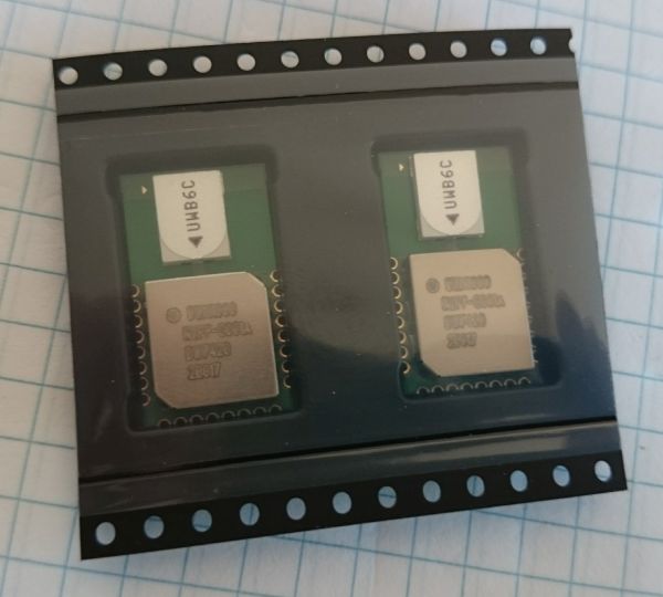
The DWM1000s have arrived:
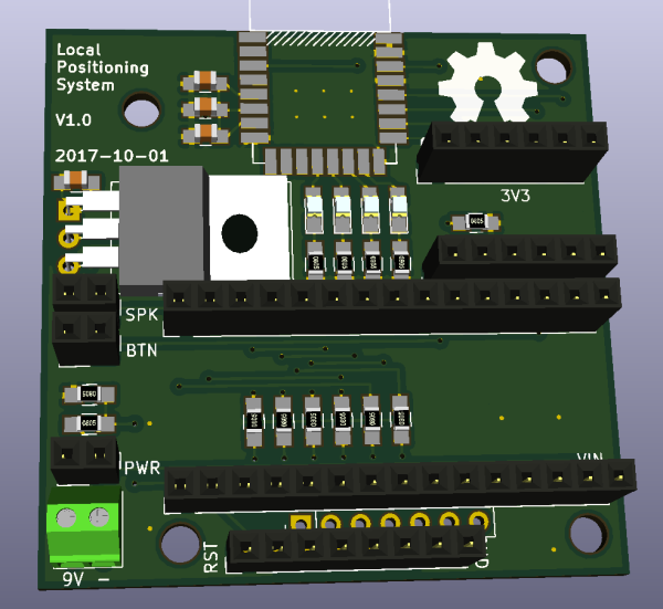
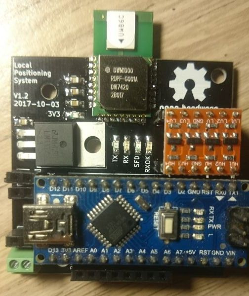
Fabricated the board. It seems to be alive! Currently running blink on the Arduino, and nothing has blown up:
Next actions:
It's alive! I ran BasicConnectivityTest.ino from the GitHub code, and:
DW1000 initialized ...

Committed configuration ...

Device ID: DECA - model: 1, version: 3, revision: 0

Unique ID: FF:FF:FF:FF:00:00:00:00

Network ID and Device Address: PAN: 0A, Short Address: 05

Device mode: Data rate: 6800 kb/s, PRF: 16 MHz, Preamble: 128 symbols (code #4), Channel: #5
Just started reading through the library... what a monumentally confusing task it is to read through other people's code. First, I need to finish the other device, then I can have the two of them talk to eachother.
Next actions:
...and the other LPS is finished. Time for some communications!
Next actions:
Both of them are alive. Now it's REALLY time to get them to communicate with MessagePingPong.ino:
Transmitted: Ping ...

Received: ... and Pong
Well, that seems to work. The power supply is definitely an issue, it seems to be sensitive. Ocasionally, the reciever will simply stop working. I would describe the apparent connectivity as sporadic.
An initial test of the range of these devices is not particularly convincing:
Range: 40.26 m RX power: -102.81 dBm Sampling: 11.94 Hz
...seemed to be the maximum range I could achieve in my back yard, and it was extremely sensitive to disturbances from the environment i.e. walls, metal. It seems to be primarily a LOS device. I'll need to test this device in a more realistic environment.
In slightly more favourable conditions (1 m wooden aerial, on a hummock, in a grassy area), the unit managed a range of around 100 m or so. With a longer aerial, I think this could be improved.
I'm begining to become concerned that this is not a good approach to solving this problem. I think that the trees are going to pose too large of an electromagnetic obstruction for the reliable operation of the device. I need to actually try using GPS, and consider acoustic or radio solutions. I need to reseach this from the ground up.
Next actions:
Well, I've had a long break from this idea. I still haven't tried GPS. Next thing to try would probably be audio TOF multilateration. I am interested in low (sub 20 Hz), medium (~ 1 kHz), and ultrasonic (above 20 kHz) frequency sound. This paper looks like it might be relevant. Another paper suggests that "Foliage attenuation contributes over a broad frequency range but most significantly above 1 kHz...". Another good summary can be found here. The main things to be concerned about are:
Low frequency sound seems much better at propogating, since the tree trunks are small compared to the wavelengths in question.
For reference: a link to a $5 pre-amp. Another technique might be to bandpass filter the audio first, and then detect peaks with an Arduino. The ultimate question is about how well the sound propogates though. Generally, lower frequencies are better, but the speakers are large.
Another potential slution lies with phase-comparison monopulse, which would allow the position to be triangulated using the angles of arrival at several beacons. This technique has many advantages, though probably requires some slightly more complicated hardware, and a powerful radio. These guys have loads more information. these guys have a few examples of appications. Looks a little expensive maybe...
Another thing worth trying is using a drone to perform the measurements, as part of the Cattle Mangement project.
Next actions:
I'm leaning towards low frequency sound as a solution. I think this will let me sample with Arduinos (part of the problem with USB sound cards is this explanation talking about crystal timings) if I really want to, which could save on cost. It also allows for good propogation through the trees, and a long signal range. Unfortunately, it also adds size and weight to the speaker. I think a first useful test would be to try to detect the output of a microphone on an analog input of an Arduino. It might be that I need a pre-amp of sorts. Let's wait and see.
Next actions:
Today I did some walking around in the farm with a GPS. I recorded the readings for post-processing with Python. I think it's important to see just how good GPS is before discarding it completely. Next step: plot movements against map. This is tricky, I essentially have to design software for this. I could use the Google Maps API to begin with, but later on I think I'm going to want something a bit more custom. I'm imagining a website where you can upload a background JPG image, calibrate the GPS coordinates of 2 points selected from the picture, and then it automatically scales with the screen, displays the coordinate of the point you're looking at, measures distances and areas, allows for JSON data uploads of different kinds for the trees, allows for upload of raw GPS data, performs realtime updates of locations...I could go on forever. Bare minimum for now:
Next actions:
I ended up making the website using the Google Maps API. I'm sure you'll agree it looks pretty neat.
Concerning the audio approach to localisation, I tried connecting a microphone directly to an Arduino, but I got no measureable reading. Aplification is definitely needed. I had a few modules with an LM393 and microphone, and connected them with great results. They're good at picking up clicking sounds, but not so good with sine waves.
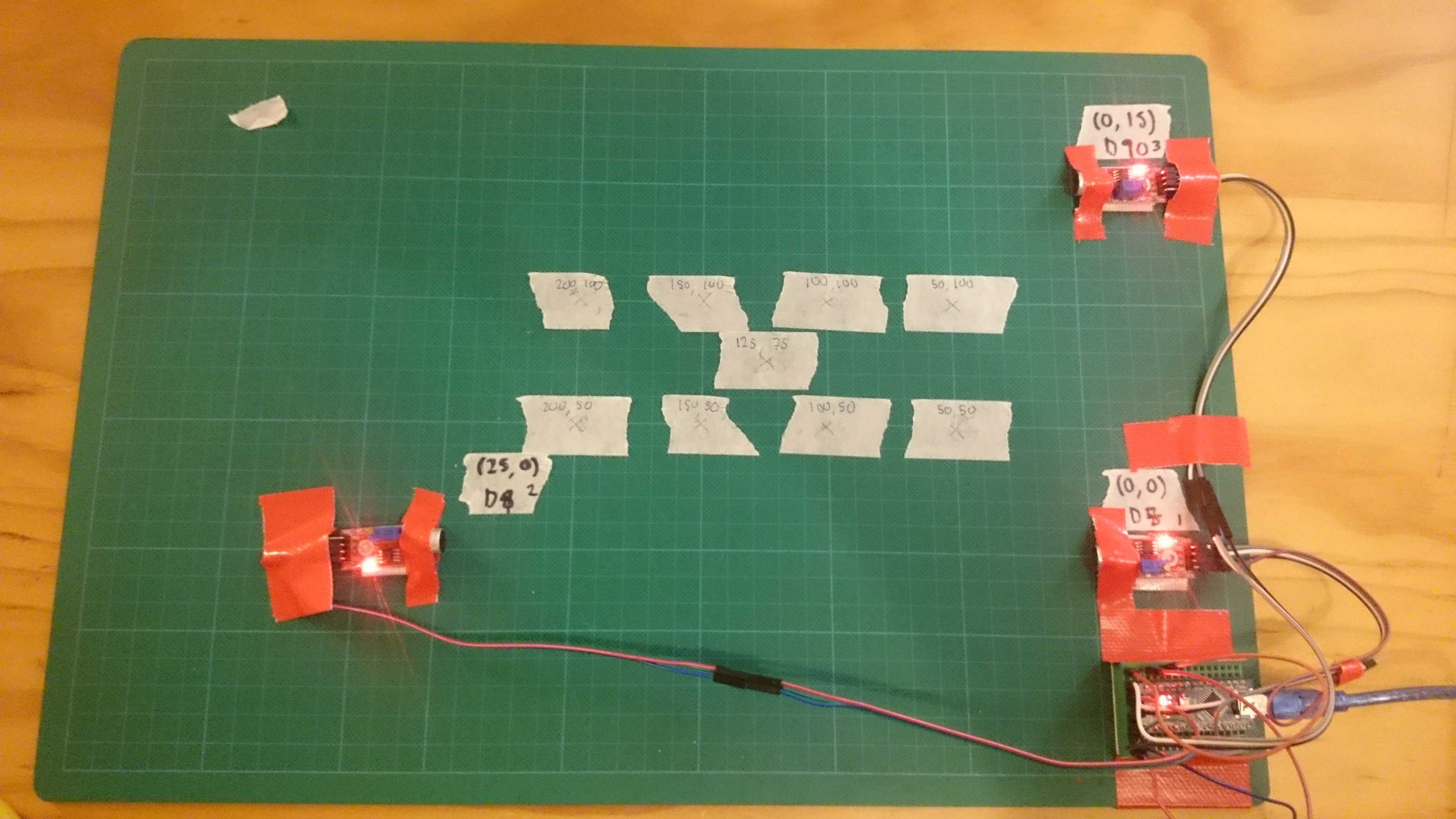
I then got on to the idea of using TDOA to measure position. The code works as follows:
The end result: sub 10 mm positioning! Pretty good when you consider that it takes just 30 microseconds for sound to travel that distance, and the Arduino opperates at 16 MHz. The code was far from optimised, but it shows a lot of promise.
The next step would be to see if an Arduino can read a sine wave, and how sensitive it can be made. Quick research suggests that lower frequencies have less attentuation, but logic asserts that dispersion and power might become more of an issue. I would guess that 100 - 1000 Hz is about right. This guide offers some useful advice for aplifying audio signals for Arduinos. Part of the trick here though, is that I want to detect only the peaks produced by the frequency of interest. I think a bandpass filter in hardware would take care of this. It's tempting to do this in software... I'll experiment later.
Next actions:
Last night I tried and failed to get a TL072 working with the micrphone I had on me. I'll try again on a bigger breadboard soon.